
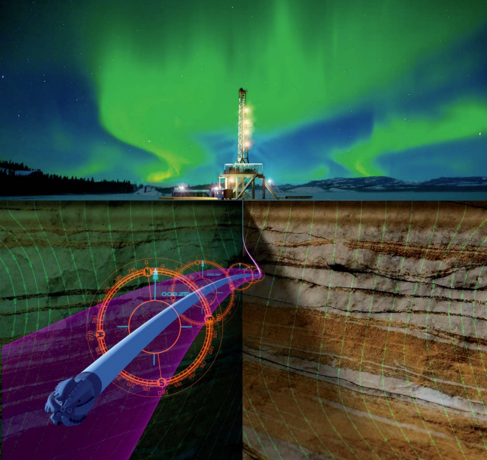
Representation of the well
The path of the well is determined by a study which gives the positions of the well at a number of points along it. The position is determined by the coordinates in the north, east and vertical directions. In addition, depth along the pit, slope and direction of the study station are included. Inertial navigation systems directly measure coordinates and calculate inclination and direction.
Location of the well
The location of a well is indicated by coordinates. These can be geographic in terms of latitude and longitude scales or grid coordinates. Earth wells are usually observed with traditional triangle techniques from existing standard stations. In remote areas without reliable standards, a Global Positioning System (GPS) using satellite navigation can be used. Offshore, there are a variety of options depending on the distance from the shore and the area of operation.
Revolving Table Height is used as a reference for work depth. For earth wells the position of the upper basement is monitored before drilling begins. To be able to reconnect to the well, a fixed level must usually be set for a flange of its head. The offshore distance from the observed sea level at the turntable is measured and then corrected for the change in relation to the Average Sea Level (MSL).
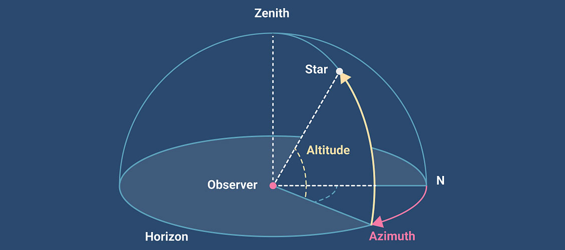
There are three azimuth reference systems:
This is the direction of the horizontal component of the Earth’s magnetic field. A magnetic compass approximates these lines.
This is the direction of the geographic North Pole, on the axis of rotation of the Earth. Direction is shown on maps by longitude meridians. Northern search throughput tools and Inertial Navigation Systems follow this reference.
Longitude meridians do not produce a rectangular lattice system. The grid lines on a map form a rectangular grid system, the northern direction of which is determined by a specified meridian of longitude, called the Northern Grid. In the Universal Transversal Mercator coordinate system the world is divided into 60 zones with 6 degrees latitude, in which the central meridian defines the Northern Grid. The North and True North grids are identical only to the central meridian.
Azimuth reference system conversions
Azimuths should be cited in the same reference system. This is usually the Grid North system. In practice, azimuths are often measured in other systems and two conversions must be applied to the measurements performed:
Network convergence: that converts azimuth values between North and True North Network. By definition, network convergence is positive when moving clockwise from True North to North Grid and negative when moving counterclockwise from True North to North Grid. Near Ecuador the convergence is small and increases with increasing latitude.
Network Correction: Network correction is the negative of network convergence.
Declination: converts azimuth values between magnetic north and true north systems. By definition, declination is positive when moving clockwise from True North to Magnetic North, and negative when moving counterclockwise from True North to Magnetic North.
The declination values vary with time and location and those that represent the parameters to be used at the time of drilling. When storing magnetic resonance imaging results, declination and date should be included.
Cross-drilling references
For management purposes, BHA (beta-hydroxy acid) should be oriented. This requires measuring the angle between the direction of the plane of the transverse pit (from the top) and a reference point marked on the outside of the bent substrate (writing line). Positioning the survey tool in a fixed orientation is performed using a key seat. The angle difference between the key seat writer line and the sloping signature line indicates the displacement of the tool page. The survey tool measures the surface of the vehicle, the angle between its fixed orientation and the top side. The angle between the scroll bar of the bent part and the top side is the sum of the displacement of the tool page. The upper side is the direction perpendicular to the drilling axis in the local vertical plane. For vertical wells, the top side is undefined.
The tool space is the angle of rotation of the tool around the drilling shaft, measured in a clockwise rotation from the top. The tool page can be measured using a bullet bob or accelerator. The tool side with a slope below 5º has not been measured accurately. A magnetic or gyroscopic device may be used in these situations. These tool sites are identical to the magnetic azimuth or real.
Vertical section (projected horizontal displacement)
The vertical view of the well path represents a graph of True Vertical Depth (TVD) versus projected horizontal displacement (PHD), in a single plane. Where the direction of the well path is more than about 20º from the target plane, the distortion of the designed well path becomes redundant and the plot is difficult to understand.
There are a number of solutions to the graphic presentation problem. The two most practical yields:
- Multiple views of vertical sections: Additional vertical views projected in the direction planes of the main pits.
- Stretch grace: This graph looks similar to the vertical section graph, but the horizontal scale is True Horizontal Displacement (the actual displacement in the horizontal plane). An alignment graph represents the horizontal displacement of the well path as if it were extending along a constant azimuth. It has the advantage that the plot is independent of azimuthi and the true slope of the pit can be seen.
Well calculations
With the exception of Inertial Navigation Systems that measure true displacement, a guided study measures slope and azimuth at a number of depth-defined observation stations along the pits. The measured values are used to calculate the North, East and True Vertical Depth coordinates within the specified reference systems. Furthermore, the stiffness of the legs and the predicted horizontal displacement (PHD) can be calculated.
There are a number of different calculation methods, however Minimal Bending is the standard generally used.
Uncertainty of pit position
The uncertainty position of the well is the limit of the actual possible positions of a study station from its calculated position. It is the result of uncertainties resulting from the survey. The magnitude of the position uncertainty describes a three-dimensional ellipsoid determined by the type, quality, and pattern of uncertainty of the observation made.